Project 1: Getting Started with ESP32
Project 1 A : Blinking an LED with ESP32
Objective
In this project, we’ll connect an LED to an ESP32 using a breadboard and jumper wires to make it blink. This is a perfect beginner project to understand basic GPIO pin functionality on the ESP32.
Components Needed:
- ESP32 microcontroller
- Breadboard
- LED (any color)
- Jumper wires
- USB cable (to connect ESP32 to your computer)
Step 1: Assembling the Circuit
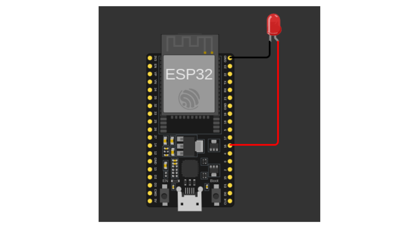
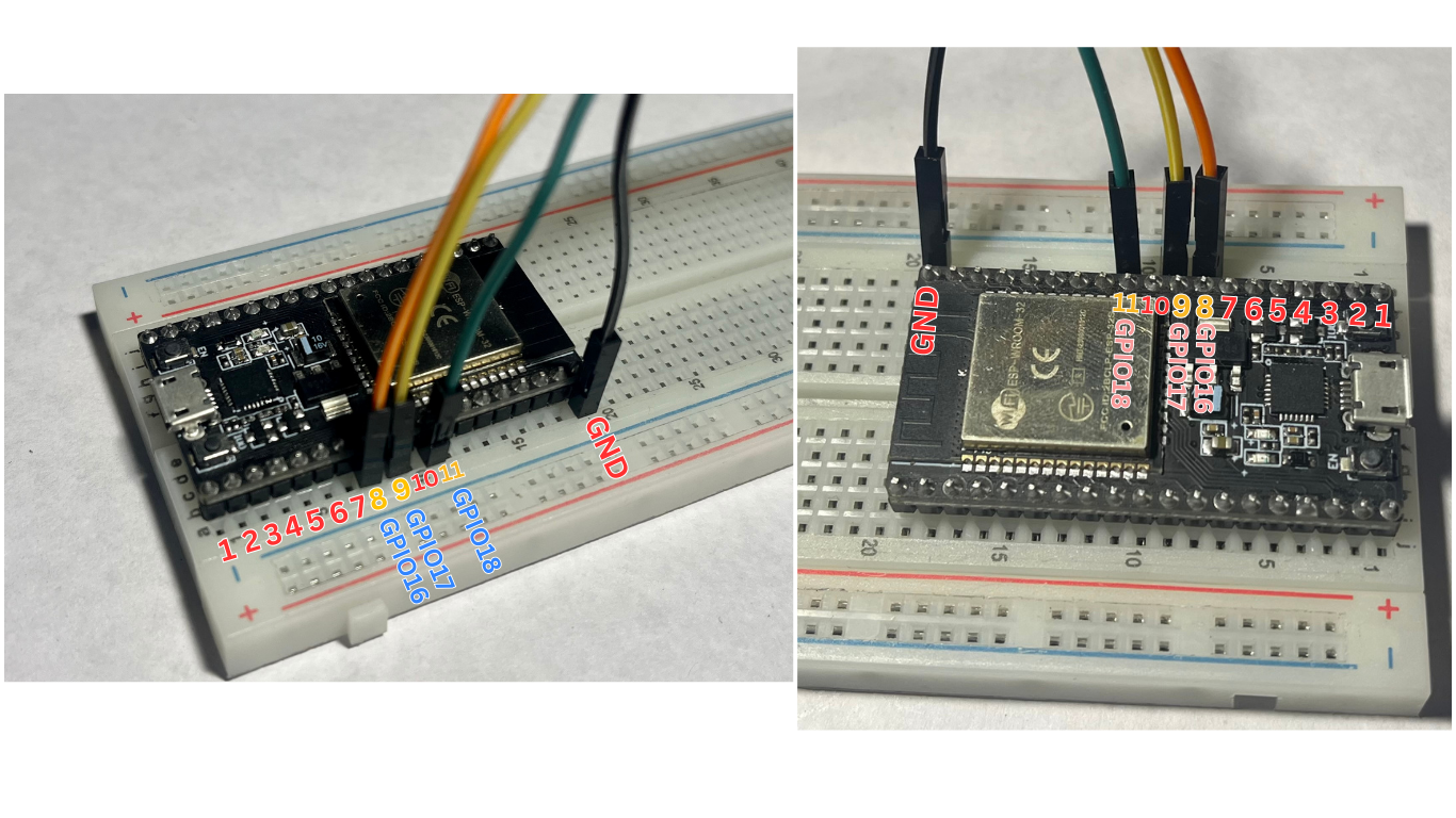
Follow these steps while referring to the breadboard diagram:
- Connect the Jumper Wires First:
- Take an orange jumper wire and connect one end to GPIO16 on the ESP32.
- Take a black jumper wire and connect one end to GND on the ESP32.

2. Place the LED on the Breadboard:
- Insert the LED into the breadboard, ensuring its legs are in separate rows.
- The longer leg (anode) is the positive side, and the shorter leg (cathode) is the negative side.
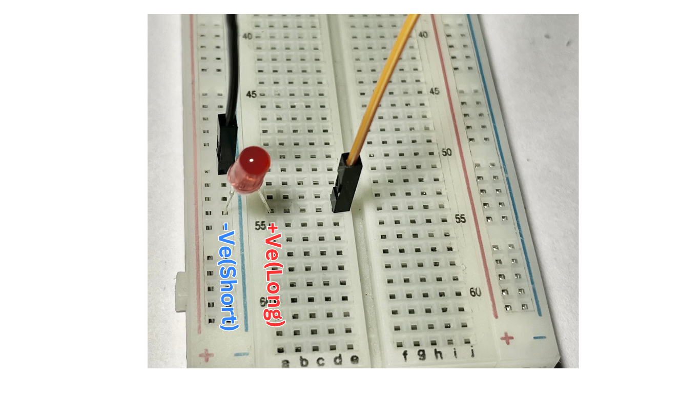
3. Connect the Jumper Wires to the LED:
- Attach the orange wire (from GPIO16) to the same row as the longer leg (anode) of the LED.
- Attach the black wire (from GND) to the same row as the shorter leg (cathode) of the LED.
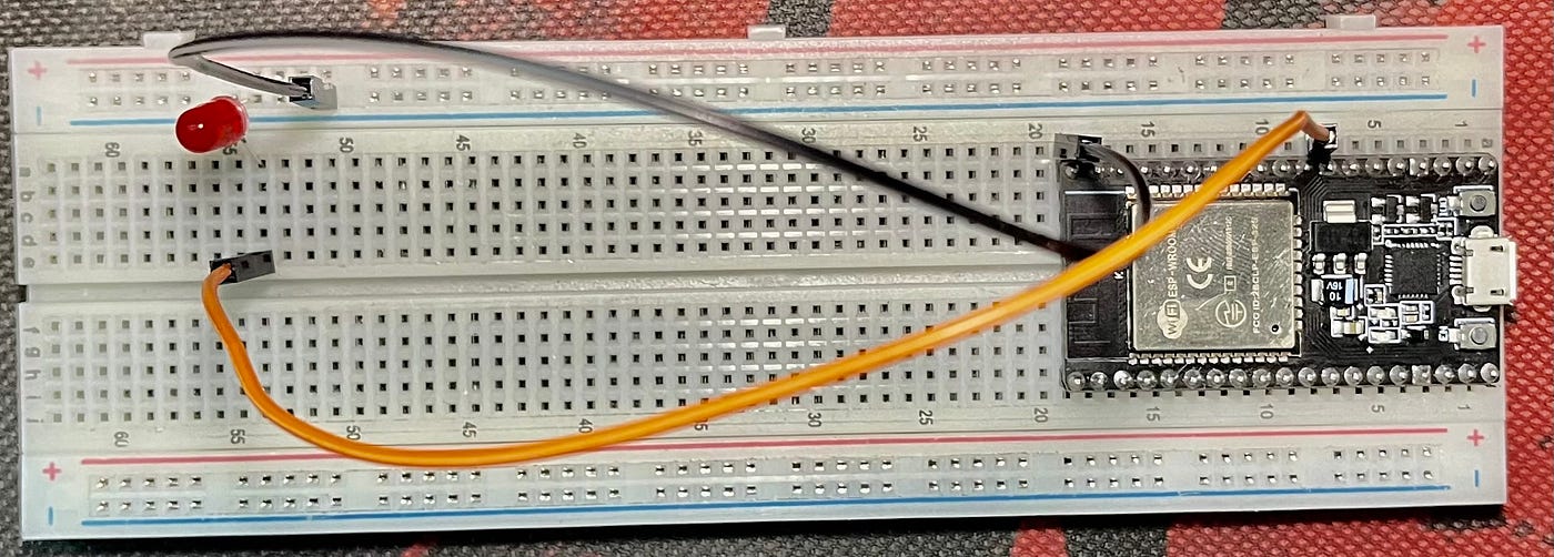
4. Double-Check the Connections:
- Ensure all connections match the breadboard diagram before powering the ESP32.
Step 2: Writing the Code
Setup Arduino IDE using the video below:
Use the following code to make the LED blink:
#define LED 16   // GPIO16 is connected to the LED
void setup() {
  pinMode(LED, OUTPUT);    // Configure LED pin as output
}
void loop() {
  digitalWrite(LED, HIGH); // Turn the LED on
  delay(1000);             // Wait for 1 second
  digitalWrite(LED, LOW);  // Turn the LED off
  delay(1000);             // Wait for 1 second
}
Code Explanation:
-
#define LED 16: Assigns GPIO16 as the pin connected to the LED. -
pinMode(LED, OUTPUT);: Sets GPIO16 as an output pin. -
digitalWrite(LED, HIGH);: Sends a high signal (3.3V) to GPIO16, turning the LED on. -
digitalWrite(LED, LOW);: Sends a low signal (0V) to GPIO16, turning the LED off. -
delay(1000);: Waits for 1 second before toggling the LED again.
Step 3: Uploading the Code
- Open the Arduino IDE on your computer.
- Go to Tools > Board > ESP32 Arduino > Select your ESP32 board.
- Select the correct port under Tools > Port.
- Copy and paste the above code into the Arduino IDE.
- Click the Upload button (right arrow icon) to send the code to the ESP32.
- Once uploaded, the LED should start blinking with a 1-second interval.
Project 1 B: Traffic Light Simulation with ESP32
What You’ll Need
- ESP32 microcontroller
- Breadboard
- Red LED
- Yellow LED
- Green LED
- Jumper wires
- USB cable (to connect ESP32 to your computer)
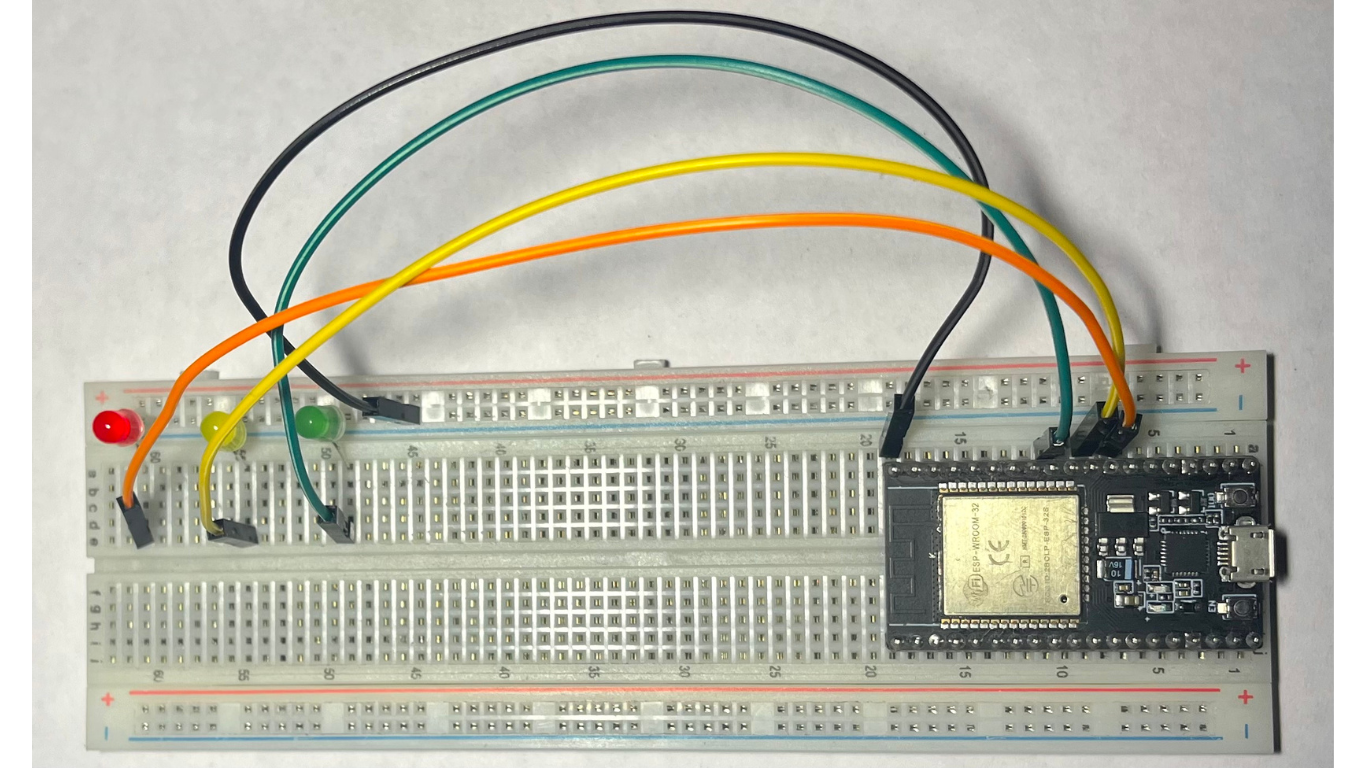
Step 1: Assembling the Circuit
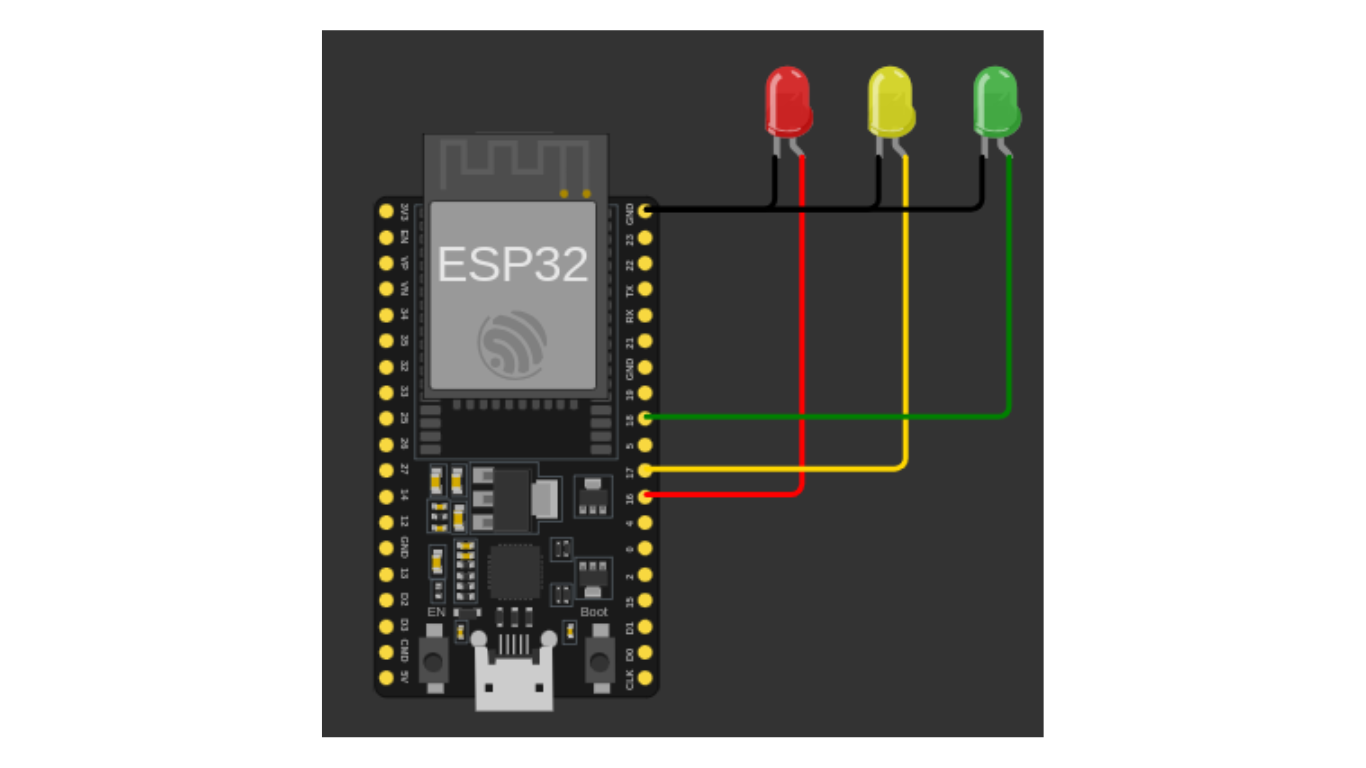
1. Place the LEDs on the Breadboard

- Place the red, yellow, and green LEDs on the breadboard in different rows.
- Ensure the anode (longer leg) of each LED is in one row and the cathode (shorter leg) is in another.
2. Connect the LEDs to the ESP32
Use jumper wires to connect:
- The anode of the red LED to GPIO16 on the ESP32.
- The anode of the yellow LED to GPIO17 on the ESP32.
- The anode of the green LED to GPIO18 on the ESP32.
- Connect the cathode (shorter leg) of each LED to the GND pin of the ESP32 using jumper wires.
3. Connect the cathode (shorter leg) of each LED to the GND pin of the ESP32 using jumper wires.
4. Double-check all connections with the circuit diagram.
Step 2: Writing the Code
Use the following code to simulate a traffic light system:
// Define LED pins
const int redPin = 16;    // Red LED
const int yellowPin = 17; // Yellow LED
const int greenPin = 18;  // Green LED

void setup() {
  // Initialize all LED pins as outputs
  pinMode(redPin, OUTPUT);
  pinMode(yellowPin, OUTPUT);
  pinMode(greenPin, OUTPUT);
}

void loop() {
  // Red light (Stop)
  digitalWrite(redPin, HIGH);
  digitalWrite(yellowPin, LOW);
  digitalWrite(greenPin, LOW);
  delay(5000);  // Red light for 5 seconds

  // Yellow light (Prepare to go)
  digitalWrite(redPin, LOW);
  digitalWrite(yellowPin, HIGH);
  delay(2000);  // Yellow light for 2 seconds

  // Green light (Go)
  digitalWrite(yellowPin, LOW);
  digitalWrite(greenPin, HIGH);
  delay(5000);  // Green light for 5 seconds
}
Code Explanation:
1. Defining Pins:
-
redPin,yellowPin, andgreenPinare assigned to GPIO16, GPIO17, and GPIO18 respectively.
2. Setup:
- All LED pins are set as outputs using
pinMode.
3. Traffic Light Logic in Loop:
-
Red light (Stop):
Turns on the red LED for 5 seconds while the others remain off. -
Yellow light (Prepare to go):
Turns on the yellow LED for 2 seconds. -
Green light (Go):
Turns on the green LED for 5 seconds while the others remain off.
Step 3: Uploading the Code
- Open the Arduino IDE on your computer.
- Go to Tools > Board > ESP32 Arduino > Select your ESP32 board.
- Select the correct port under Tools > Port.
- Copy and paste the above code into the Arduino IDE.
- Click the Upload button (right arrow icon) to send the code to the ESP32.
- Once uploaded, the LEDs should start simulating a traffic light system.